Introduction
What is an Entity Relationship Diagram (ERD)?
Entity Relationship Diagrams, commonly known as ERDs, are powerful visual tools that depict the relationships between various data entities within a database. Imagine them as blueprints for a building; instead, they lay out the data structure and its interactions. Each entity in an ERD represents a distinct concept or object (like a "Customer" or "Order"), while lines connecting them illustrate how these entities interact.
An ERD typically includes:
- Entities: Objects or concepts (e.g., Customer, Product).
- Attributes: Descriptive properties of entities (e.g., Customer Name, Product Price).
Importance of ERDs in Database Design
The significance of ERDs in database design cannot be overstated. They clarify and facilitate communication among stakeholders, such as developers, database administrators, and business analysts.
Benefits include:
- Streamlined communication: Helps everyone understand the data structure.
- Efficient design: Aids in identifying potential issues early in the development process.
- Improved documentation: Serves as a valuable reference for future maintenance and updates.
By leveraging ERDs, organizations can ensure a more effective and organized approach to database design.
Basic Concepts of ERDs
Entities and Attributes
At the heart of an ERD are entities and attributes. Entities represent the core components of a database, such as "Student" or "Course." Think of them as nouns in the world of data. Attributes, on the other hand, are the descriptive pieces of information about those entities—like "Student ID," "Name," or "Email." For instance, you can visualize a "Book" entity that has attributes such as "Title," "Author," and "ISBN."
Relationships
Next, we have relationships that connect entities. These relationships define how entities interact with one another. For example, a "Student" can enrol in multiple "Courses," and each "Course" can have many "Students."
Cardinality and Modality
Understanding cardinality and modality is crucial in detailing these relationships. Cardinality refers to the numerical relationships between entities:
- One-to-One: Each entity relates to a single entity (e.g., each person has one passport).
- One-to-Many: One entity relates to multiple entities (e.g., one teacher can teach many students).
- Many-to-Many: Multiple entities relate to others (e.g., students enrolled in multiple courses).
Modality indicates whether the relationship is optional or mandatory. For instance, if a "Course" must have at least one "Student," this relationship is required. Understanding these concepts is foundational for creating accurate and effective ERDs.
Components of ERDs
Entity Sets
In an ERD, entity sets are foundational components that group similar entities. Each entity set contains a collection of related objects, like all the "Employees" in a company. Visualizing these as boxes in your diagram helps define the scope of your database. For instance, an entity set for "Products" could include various products a retail store sells.
Relationship Sets
Next, we have relationship sets. These define how different entity sets interact with one another. Think of it as the connections in a social network; they reflect the links between entities. For example, you might have a relationship set called "Orders," linking "Customers" to the "Products" they purchase. This clarifies how one entity influences another.
Attributes
Lastly, attributes are the specifics that describe entities or relationships. Attributes provide essential details, such as a "Customer" entity having attributes like "Customer ID," "Name," and "Address." By clearly laying out these attributes in your ERD, you ensure that important information is not overlooked, making your database more robust and user-friendly.
Types of Relationships in ERDs
One-to-One
Understanding the types of relationships in ERDs is crucial for creating accurate schema designs. One-to-one relationships indicate that each entity in one set is linked to a single entity in another set. For example, consider a "Person" entity and a "Passport" entity. Each person can own only one passport associated with a specific person. This relationship simplifies tracking unique attributes like personal details.
One-to-Many
The One-to-Many relationship is more common and is a vital link between entities. In this scenario, a single entity can relate to many entities in another set. For instance, a "Customer" can place multiple "Orders," but just one customer places each order. This relationship allows organizations to track the purchasing patterns of customers effectively.
Many-to-Many
Lastly, the Many-to-Many relationship provides a dynamic interaction between entities. In this case, one entity can relate to multiple entities and vice versa. A great example is "Students" and "Courses"—students can enrol in various courses, and each course can have many students. This complex relationship often requires an intermediary entity to manage the connections, ensuring all interactions are accurately captured. Database designers create a more flexible and effective relational model by recognising and implementing these relationships.

Notations and Symbols in ERDs
Crow's Foot Notation
When representing ERDs, notation is vital for clarity and communication. One popular style is Crow's Foot Notation. This method uses distinct symbols to illustrate relationships and cardinality, where a simple line ends with a "crow's foot" to indicate "many." For example, a single line connecting a "Customer" entity to a "Order" entity, with a crow's foot at the "Order" end, clearly shows that one customer can place many orders.
Chen Notation
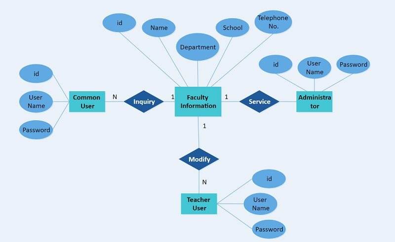
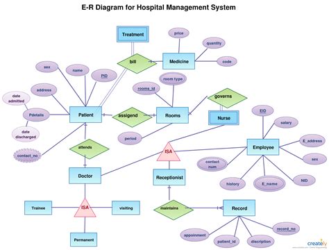
Next, let's talk about Chen Notation. Peter Chen's notation emphasizes clarity by using rectangles for entities, diamonds for relationships, and ovals for attributes. This visual distinction helps users quickly identify component types at a glance. For instance, if you see a diamond linking two rectangles, you immediately recognize a relationship between those entities.
UML Notation
Lastly, UML Notation (Unified Modeling Language) is another widely used method, especially in software engineering. UML diagrams streamline the design process by combining ERD principles with more extensive modelling techniques. In UML, classes represent entities, while associations indicate relationships. This notation is helpful when developing object-oriented applications and can efficiently represent complex data structures.
Choosing the right notation can enhance the understanding and usability of an ERD, making it easier for stakeholders to interpret the database design effectively.
Steps to Create an ERD
Identify Entities and Relationships
Creating a robust Entity Relationship Diagram (ERD) starts with identifying entities and relationships. Begin by listing all the concepts relevant to your database, such as "Customer," "Order," and "Product." Next, establish how these entities interact. For instance, a "Customer" can place many "Orders," which forms the basis of your relationships.
Define Attributes
Once you have your entities and relationships outlined, it’s time to define attributes. Attributes describe essential details for each entity. For example, the "Customer" entity might have attributes like "Customer ID," "Name," and "Email Address." By clearly listing these attributes, you ensure that essential information is encapsulated within your ERD.
Determine Primary Keys
Lastly, identifying primary keys is essential for maintaining data integrity. A primary key uniquely identifies each entity instance. For your "Customer" entity, "Customer ID" could serve as the primary key, ensuring that each customer is distinct. This process not only aids in data retrieval but also reduces redundancy. These steps will create a compelling and organized ERD, setting a strong foundation for your database design.
Tools for Creating ERDs
Lucidchart
With the foundational elements of an ERD in place, utilizing practical tools can significantly enhance the design process. Lucidchart is popular among professionals due to its user-friendly interface and collaborative features. It allows users to drag and drop shapes quickly, making it simple to create complex diagrams. Plus, the ability to share in real-time streamlines teamwork, especially for remote teams.
Microsoft Visio
Another powerful tool is Microsoft Visio, which many organizations prefer for its robustness. Visio offers advanced features tailored for creating detailed ERDs, such as templates, stencils, and specialized symbols. If you're already familiar with Microsoft Office products, you’ll find it integrates seamlessly into your workflow—making it a sensible choice for those who need to create comprehensive diagrams quickly.
Draw.io
Finally, Draw.io (now known as diagrams.net) is a fantastic free option that offers impressive functionality without the price tag. This web-based tool is ideal for individuals or businesses on a budget. It features a simple drag-and-drop interface with versatile options for saving and sharing diagrams. Plus, it supports cloud storage for easy accessibility.
Selecting the right tool can streamline the process of creating effective ERDs and improve collaboration among team members.
Examples of ERD Diagrams
Simple Database Example
To illustrate the concepts covered, let’s look at a simple database example. Imagine a small library system. In this ERD, we might have entities like "Books," "Authors," and "Members." The relationships are straightforward: a "Member" can borrow many "Books," and each "Book" can be written by one or more "Authors." This clarity makes it easy for staff to understand the borrowing process and manage inventory efficiently.
Advanced ERD Example
Now, consider an advanced ERD example for a university system. This can become intricate, featuring entities like "Students," "Courses," "Professors," and "Departments." Here, you may find relationships such as "Students enrol in Courses," "Professors teach courses," and "Professors belong to Departments." With many-to-many relationships, a junction table may effectively link students to courses.
Such advanced ERDs can help universities keep track of complex interactions and improve overall academic management. By examining these examples, one can grasp the versatility and applicability of ERDs across different scenarios.
Best Practices for Designing ERDs
Keep It Simple
When embarking on the journey of designing ERDs, one of the top best practices is to keep it simple. Complexity can cloud understanding and lead to mistakes down the line. Aim for clarity by including only essential entities and relationships. For example, rather than complicating diagrams with unnecessary details, focus on core elements that convey the main structure.
Use Consistent Naming Conventions
Another crucial practice is to use consistent naming conventions throughout your diagram. Consistency enhances readability and fosters better communication among team members. For instance, if you name an entity "Customer," stick to that nomenclature instead of varying it with "Client" elsewhere. To create uniformity, adopt standards across your diagrams, such as capitalization or pluralization.
Validate and Refine
Lastly, it’s essential to validate and refine your ERD continuously. Engage team members for feedback and test the diagram against real-world scenarios. This iterative process helps identify gaps or inaccuracies. For example, simulating queries based on the ERD can reveal if relationships and attributes are accurately represented. By following these best practices, you'll craft effective, maintainable, and user-friendly ERDs that stand the test of time.
Common Mistakes to Avoid in ERDs
Overcomplicating Relationships
As you design your ERD, one of the common mistakes to avoid is overcomplicating relationships. While including every possible interaction between entities is tempting, this can lead to confusion and clutter. For example, having too many arrows and lines can make it difficult for viewers to grasp the essential connections. Instead, focus on the most significant relationships and use more straightforward diagrams for secondary interactions.
Neglecting Cardinality
Another pitfall is neglecting cardinality in your relationships. Cardinality specifies how entities interact regarding quantity—such as one-to-one or many-to-many. Misrepresenting these relationships can lead to significant data integrity issues. For instance, failing to indicate that a "Student" can enrol in multiple "Courses" can mislead database users about the system’s capabilities.
Missing Entities or Attributes
Finally, missing entities or attributes can create gaps in your database design, resulting in incomplete structures that fail to meet business needs. For example, if a "Product" entity lacks attributes like "Product Price" or "Product Description," it can hinder effective product management. Regularly review your ERD to ensure all critical components are included, leading to a more comprehensive and functional database design. By steering clear of these mistakes, you’ll enhance the clarity and efficiency of your ERDs.
Applications of ERDs
Database Design
The versatility of Entity Relationship Diagrams (ERDs) makes them invaluable across various domains. One prominent application is in database design. ERDs provide a clear blueprint of data structures, helping developers visualize how different entities interact. This clarity aids in optimizing database design to improve performance and ensure data integrity.
Business Process Modeling
Another significant application is in business process modelling. By mapping out entities and their relationships, organizations can streamline operational workflows. For instance, an ERD can illustrate how customer information is processed through various departments, highlighting inefficiencies or redundancies. This visualization empowers teams to refine business processes for better performance.
System Analysis
Lastly, ERDs play a crucial role in system analysis. They facilitate requirements gathering by representing the data aspects of systems. Analysts can use ERDs to communicate with stakeholders, ensuring that all necessary data elements are captured before moving into the implementation phase. This proactive approach minimizes costly revisions and fosters a more effective development process. By leveraging ERDs within these applications, organizations enhance their understanding, clarity, and efficiency in managing data systems.
Conclusion
Recap of Key Learnings
We’ve discussed the vital components of ERDs, from entities and attributes to the various relationship types. Understanding notations like Crow's Foot and Chen allows for more transparent communication in database design. Moreover, we examined the best practices and common pitfalls that can enhance or hinder the effectiveness of your ERDs.
Importance of ERDs in Data Modeling
The importance of ERDs in data modelling cannot be overstated. They serve as blueprints that guide database development, ensuring that all data elements are accurately captured and interrelated. By visually representing data structures, ERDs facilitate better understanding among team members, streamline processes, and enhance overall project efficiency. Ultimately, investing time in creating detailed ERDs pays off, leading to robust databases that can adapt and grow with organizational needs.


